JK flip-flop
Table of contents
Introduction
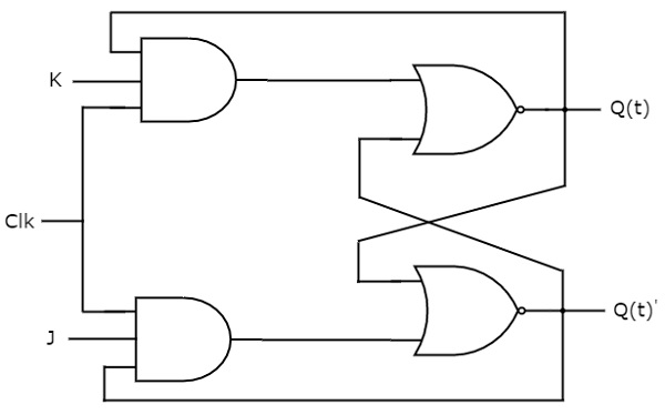
JK flip-flop is the modified version of SR flip-flop. It operates with only positive clock transitions or negative clock transitions. The circuit diagram of JK flip-flop is shown in the following figure.

This circuit has two inputs J & K and two outputs Q(t) & Q(t)’. The operation of JK flip-flop is similar to SR flip-flop. Here, the inputs of SR flip-flop are considered as S = J Q(t)’ and R = KQ(t) in order to utilize the modified SR flip-flop for 4 combinations of inputs.
State table
| J | K | Q(t+1) |
|---|---|---|
| 0 | 0 | Q(t) |
| 0 | 1 | 0 |
| 1 | 0 | 1 |
| 1 | 1 | Q(t)’ |
Here, Q(t) & Q(t + 1) are present state & next state respectively. So, JK flip-flop can be used for one of these four functions such as Hold, Reset, Set & Complement of present state based on the input conditions, when positive transition of clock signal is applied.
Characteristic table
| J | K | Q(t) | Q(t+1) |
|---|---|---|---|
| 0 | 0 | 0 | 0 |
| 0 | 0 | 1 | 1 |
| 0 | 1 | 0 | 0 |
| 0 | 1 | 1 | 0 |
| 1 | 0 | 0 | 1 |
| 1 | 0 | 1 | 1 |
| 1 | 1 | 0 | 1 |
| 1 | 1 | 1 | 0 |
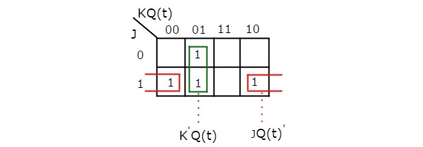
By using three variable K-Map, you can get the simplified expression for next state, Q(t + 1). The three variable K-Map for next state, Q(t + 1) is shown in the following figure.

The maximum possible groupings of adjacent ones are already shown in the figure. Therefore, the simplified expression for next state Q(t+1) is
Q(t + 1) = J.Q(t)' + K'.Q(t)