N-Bit parallel adder
Table of contents
Introduction
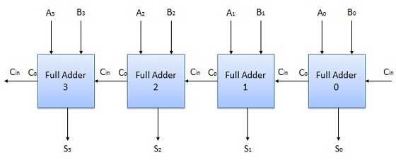
The Full Adder is capable of adding only two single-digit binary number along with a carry input. But in practice, you need to add binary numbers which are much longer than just one bit. To add two n-bit binary numbers you need to use the n-bit parallel adder. It uses several full adders in cascade. The carry output of the previous full adder is connected to carry input of the next full adder.
4-bit parallel adder
In the block diagram, A0 and B0 represent the LSB of the four-bit words A and B.
Hence Full Adder-0 is the lowest stage. Hence its Cin has been permanently made 0. The rest of the connections are the same as those of n-bit parallel adder is shown in fig. The four-bit parallel adder is a very common logic circuit.
Block diagram

N-bit parallel subtractor
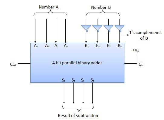
The subtraction can be carried out by taking the 1’s or 2’s complement of the number to be subtracted. For example, you can perform the subtraction (A-B) by adding either 1’s or 2’s complement of B to A. That means you can use a binary adder to perform the binary subtraction.
4-bit parallel subtractor
The number to be subtracted (B) is first passed through inverters to obtain its 1’s complement. The 4-bit adder then adds A and 2’s complement of B to produce the subtraction. S3 S2 S1 S0 represents the result of binary subtraction (A-B) and carry output Cout represents the polarity of the result. If A > B Cout = 0 and the result of binary form (A-B) then Cout = 1 and the result is in the 2’s complement form.
Block diagram
