D flip-flop
Table of contents
Introduction
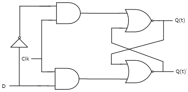
D flip-flop operates with only positive clock transitions or negative clock transitions. Whereas, D latch operates with enable signal. That means, the output of D flip-flop is insensitive to the changes in the input, D except for active transition of the clock signal. The circuit diagram of D flip-flop is shown in the following figure.

This circuit has single input D and two outputs Q(t) & Q(t)’. The operation of D flip-flop is similar to D Latch. But, this flip-flop affects the outputs only when positive transition of the clock signal is applied instead of active enable.
State table
| D | Q(t+1) |
|---|---|
| 0 | 0 |
| 1 | 1 |
Therefore, D flip-flop always Hold the information, which is available on data input, D of earlier positive transition of clock signal. From the above state table, the next state equation can be directly written as
Q(t + 1) = D
Next state of D flip-flop is always equal to data input, D for every positive transition of the clock signal. Hence, D flip-flops can be used in registers, shift registers and some of the counters.