T flip-flop
Table of contents
Introduction
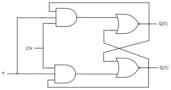
T flip-flop is the simplified version of JK flip-flop. It is obtained by connecting the same input ‘T’ to both inputs of JK flip-flop. It operates with only positive clock transitions or negative clock transitions. The circuit diagram of T flip-flop is shown in the following figure.

This circuit has single input T and two outputs Q(t) & Q(t)’. The operation of T flip-flop is same as that of JK flip-flop. Here, the inputs of JK flip-flop are considered as J = T and K = T in order to utilize the modified JK flip-flop for 2 combinations of inputs. So, the other two combinations of J & K are eliminated, for which those two values are complement to each other in T flip-flop.
State table
| D | Q(t+1) |
|---|---|
| 0 | Q(t) |
| 1 | Q(t)’ |
Here, Q(t) & Q(t + 1) are present state & next state respectively. So, T flip-flop can be used for one of these two functions such as Hold, & Complement of present state based on the input conditions, when positive transition of clock signal is applied.
Characteristic table
| T | Q(t) | Q(t + 1) |
|---|---|---|
| 0 | 0 | 0 |
| 0 | 1 | 1 |
| 1 | 0 | 1 |
| 1 | 1 | 0 |
From the above characteristic table, the next state equation can be directly written as:
          Q(t + 1) = T'.Q(t) + T.Q(t)'
          => Q(t + 1) = T ⊕ Q(t)
The output of T flip-flop always toggles for every positive transition of the clock signal, when input T remains at logic High (1). Hence, T flip-flop can be used in counters.